Testing alternate magnetic encoders

The moteus controller, uses an absolute magnetic encoder to sense the position of the rotor and thus be capable of field oriented control FOC of brushless motors. To date, all the iterations of the controller have used the AS5047P encoder from ams. This is relatively common, works fine over SPI and hasn’t caused any problems. While investigating some other issues, I decided to take a stab at trying some alternate encoders. First, I tried the AS5047U, which is the same basic encoder, but incorporates a digital filter. I also tried the MA732, from Monolithic Power, which uses a different operating principle and also includes a digital filter. The plus side of the MA732 is that it reports full 16 bit values, even if not all of them provide a lot of value.

Initial dynamometer assembly

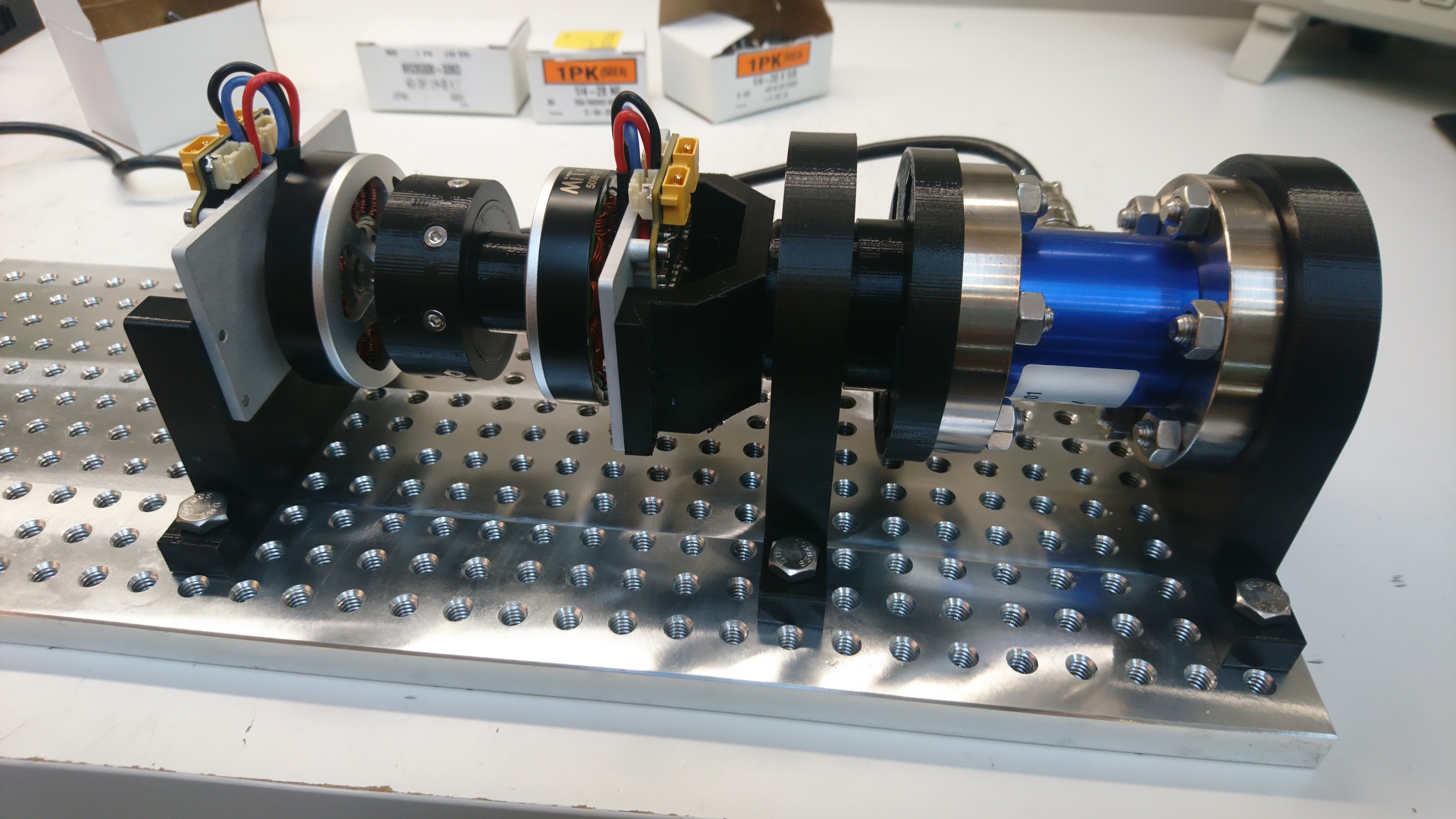
Earlier I showed off a torque transducer and the calibration fixture I used for it. I’ve now got enough assembled to make an entire dynamometer:

This has the torque transducer on one end, coupled to the “fixture” moteus controller through a bearing support. Then that is connected via a 3d printed coupler to the “device under test” moteus controller, which is hard mounted to the base plate. Any net torque between the two controllers will be coupled back to the transducer resulting in a measured torque.

Measuring voltage ripple on moteus r4.3

In another discord moment, someone was asking about the difference between electrolytic capacitors and multi-layer ceramic capacitors. That, plus some desire to re-rate the moteus, inspired me to do another sweep and measure the DC bus voltage ripple for various power levels. I captured this plot with a 24V power supply, with a 5008 motor with 0.061 ohm of winding resistance or so, and each current being applied for 300ms. The voltage ripple is peak to peak measured at the power connector.

Torque transducer

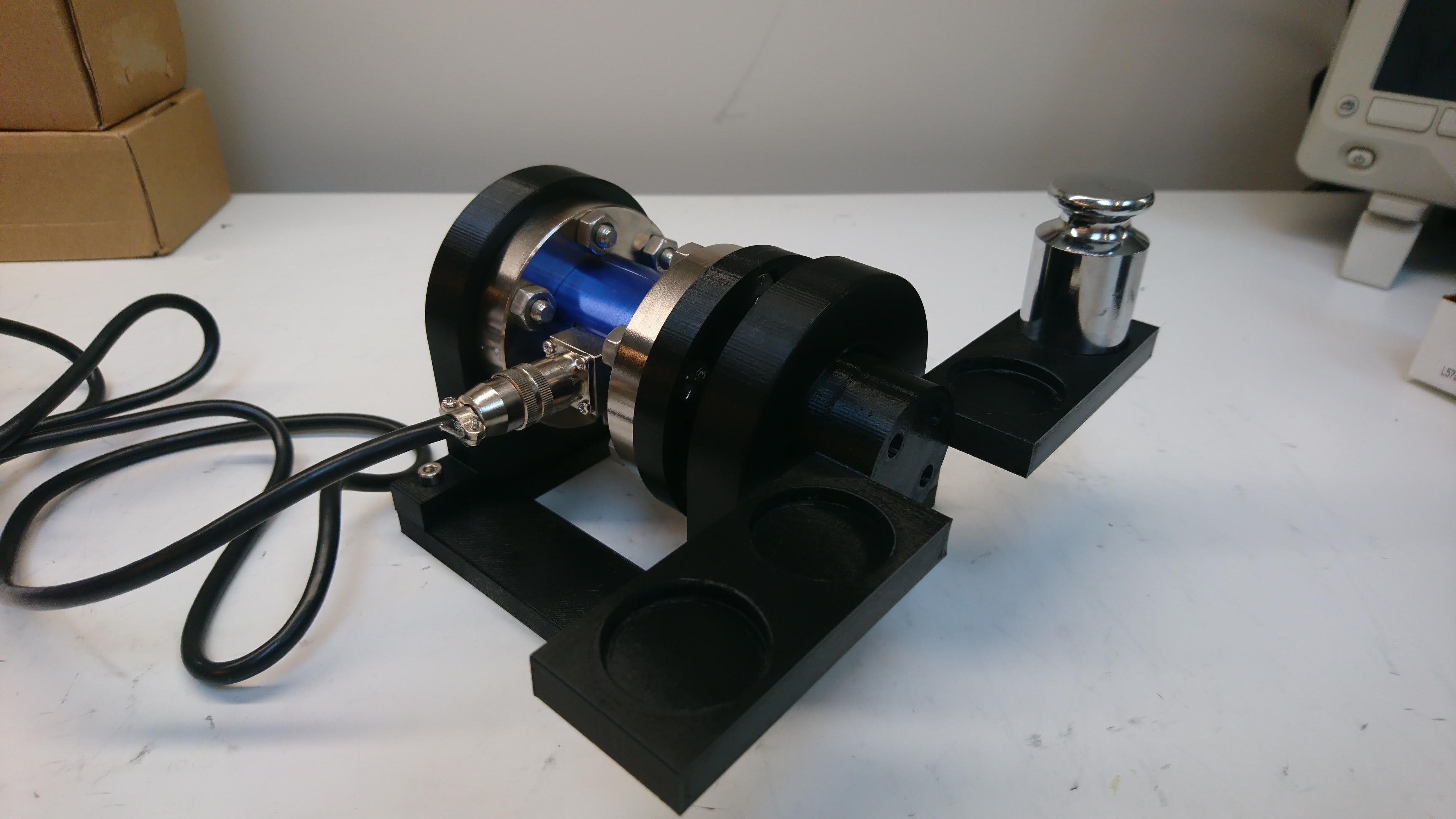
I’ve been wanting to build a dynamometer for a while to better characterize the performance of the direct drive and geared versions of the moteus controller. I have now started down that path with a torque transducer, which I calibrated with the below fixture:

I got a what ended up being a low quality load cell amplifier to use with it from the same supplier, although discovered it was total garbage and am now using a SparkFun OpenScale board which seems to be working much better. Soon I’ll hopefully have something wired up that actually has a controller or two on it.

First look at higher speed gaits

I’ve started some development on higher speed gaits for the quad A1! No real details to report now, just a video showing the first time I tested it not in simulation. I will admit these clips were cherry-picked, as there are problems still, but it is a start!

Up-rating the qdd100 beta thermal bounds

When I first posted the qdd100 beta on mjbots.com, I performed a simple “continuous torque” test where I measured the torque that could be applied indefinitely without thermal limiting in a lab environment. It has come to my attention that other servos rate their “continuous torque” for a much lower value of “continuous”, sometimes only 30s. To make the situation clearer, I measured the time to thermal limiting at a range of torques and updated the product page.

quad A1 stand-up sequence part N

I’ve worked through a number of different iterations of the stand-up sequence for the quad A1 (2019-05, 2019-09). The version I’ve been using for the last 6 months or so works pretty well, but because it drags the legs along the ground to get them into position, it can have problems when operating on surfaces with a lot of traction, like EVA foam, besides being uselessly noisy.

To make things just a bit more robust, I’ve now tweaked the startup routine so that the shoulders lift legs clear off the ground before positioning the legs, then lowers them back down into place. This makes the stand up routine much more likely to succeed on just about any surface:

Dealing with stator magnetic saturation

In my previous experiments demonstrating torque feedback (full rate inverse dynamics, ground truth torque testing), I’ve glossed over the fact that as the stator approaches magnetic saturation, the linear relationship between torque and current breaks down. Now finally I’ll take at least one step towards allowing moteus to accurately work in the torque domain as motors reach saturation.

Background

The stator in a rotor consists of windings wrapped around usually an iron core. The iron in the core consists of lots of little sub-domains of magnetized material, that normally are randomly oriented resulting in a net zero magnetic field. As current is applied to the windings, those domains line up, greatly magnifying the resulting magnetic field. Eventually most of the sub-domains are aligned, at which point you don’t get any more magnifying effect from the iron core. In this region, the stator is said to be “saturated”. You can read about it in much more depth on wikipedia or with even more detail here. The end result is a curve of magnetic field versus applied current that looks something like this: