As part of some experimentation in native Windows tools for moteus, I’ve created a dirt simple rules_wix repository in github. It provides a minimal wrapper around the WiX Toolset for creating Window’s installers from within bazel. There’s nothing fancy there yet, but it can at least make an installer with a single executable in it!
In the last post, I described the newer gait engine which takes a desired command and produces a set of gait parameters. At that point, the gait engine needs to implement those gait parameters in a way that is stable with respect to disturbances and keeps the two legs properly out of phase with one another.
The gait variables that the gait selection procedure emits are as follows, each “leg” is actually a pair of legs.
As hinted in my earlier video I’ve been working towards some higher speed gaits with the quad A1. To accomplish that, I had to restructure the gait sequencing logic to permit changing cycle times and allow flight phases.
For now, I’ve tentatively broken down the trot gait into 5 regimes, based on how fast the machine is moving:
At the slowest speeds, the flight legs swing through a step in the configured maximum flight time. The interval between flight times is fixed at a configured maximum. Here the speed is determined by how far the flight legs move.
Once the flight legs are moving through their maximum allowed distance, then the amount of time spent with both legs on the ground is reduced in order to increase speed.
At the point when both legs are not on the ground at the same time, then there begins to be a flight phase. Increasing the length of the flight phase increases the speed.
When the flight phase reaches a configured maximum, then the swing time is decreased until it reaches a configured minimum.
When the swing time is at a configured minimum, the flight time is at a configured maximum, and the legs are moving through their maximum range, then the machine is moving at its maximum speed.
Depending upon the current commanded rotation rate and translation velocity, the distance available for the legs to travel through may change. This uses the same mechanism from the step selection technique to determine the maximum distance at each update cycle, then selects which of the above regimes is active based on the commanded speed.
Here’s another short video only update, I’ve been experimenting with flight phases on the quad A1. With the gait formulation as I have it now, it isn’t terribly stable, but with some coaxing videos are possible:
The moteus controller has always supported multiple turns when counting positions. It has a one-revolution magnetic encoder built in, but after turn on, it keeps track of how many turns have occurred. However, if you’ve followed previous moteus tutorials, you have probably noticed a persistent caveat that for accurate control, the position of the output shaft needs to stay within a hundred revolutions of 0.0 or so. Now, I’ll describe why that was, and what I’ve done to remove the limitation, allowing unlimited rotations!
At the request of @nichols in discord, I’ve recently implemented a new control mode in the moteus controller, “stay within”. In this mode, as long as the controller is inside the currently commanded bounds, only a feedforward torque is commanded. When either of the optional lower or upper bound is violated, the normal PID controller is used to force the position back to the bound.
Here’s a quick video demo:
Note that this could have been roughly accomplished in a couple of ways by a higher level controller – either by monitoring the position and commanding zero kp/kd scales when inside the boundary, or just solely commanding feedforward torques based on position sensing. However, this approach lets the control run at the full 40kHz of the moteus controller, which results in much smoother operation at the boundary condition.
The moteus controller uses a DRV8323 smart driver IC to drive the power MOSFETs as well as provide various safety functions. One of the capabilities it has which has so far been unexplored in moteus is its ability to control the drive strength and dead time through software configuration.
In a switching power supply or switching motor inverter, MOSFETs are arranged in a half bridge configuration. Depending upon the type of converter, one or more half bridges are used (3 phase inverters like moteus use 3 of them). Each “half bridge” has two MOSFETs, one connected between positive power and the output terminal, and the other connected between the output terminal and ground.
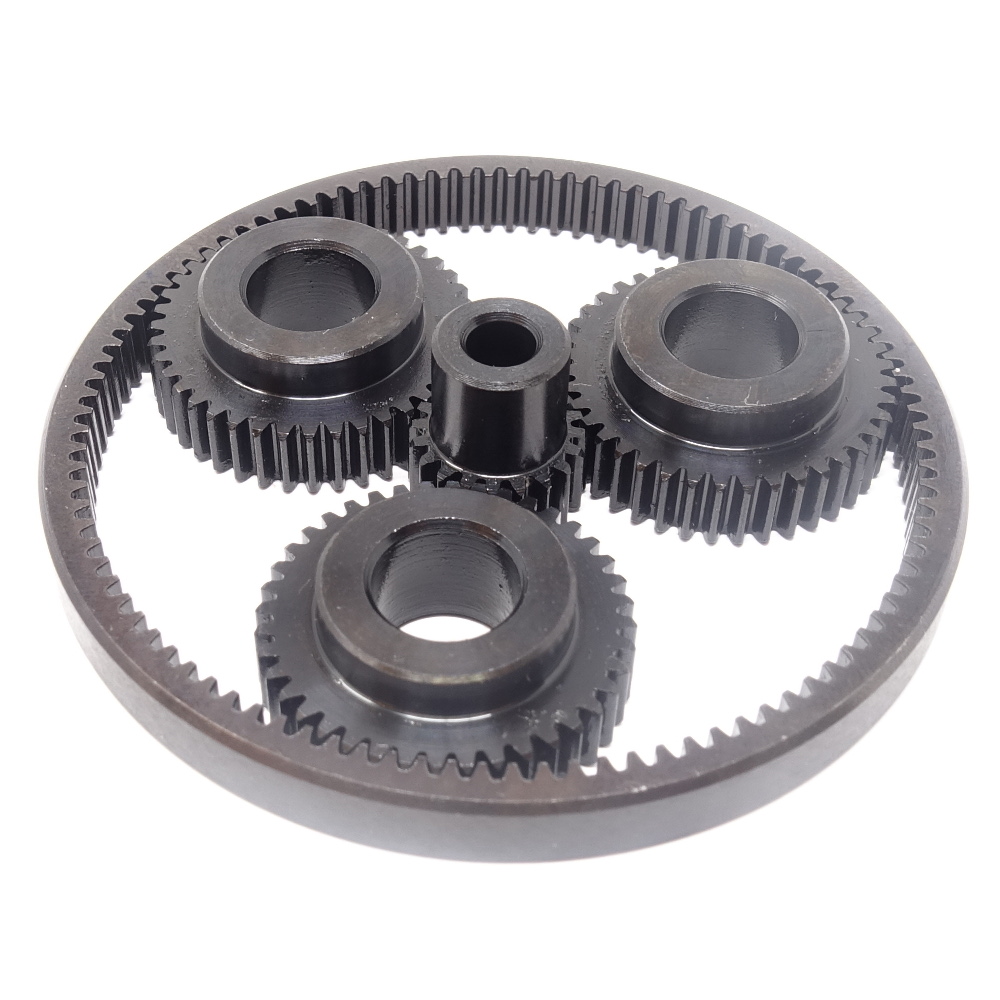
I’ve got the 6x reduction planetary gearsets back in stock at mjbots.com, now combined into a single product listing for only a little more than the old ring gear – $25 for the whole set! Compare that to the $41 you needed for an entire gearset before!
I’m continuing to make progress with getting the quad A1 to move at higher speeds, furthering my earlier video update. I’ll write up more later, but here’s a quick snapshot showing a 2 m/s trot:
This release has a number of minor improvements in the host tools (for which there continue to be no distributed binaries, you get to build from source). The biggest improvement in the firmware is the improved low-torque operation as documented here and here. If you have any questions or want help upgrading, hop into discord at #moteus and ask!