moteus r4.8

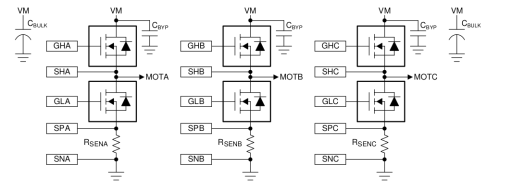
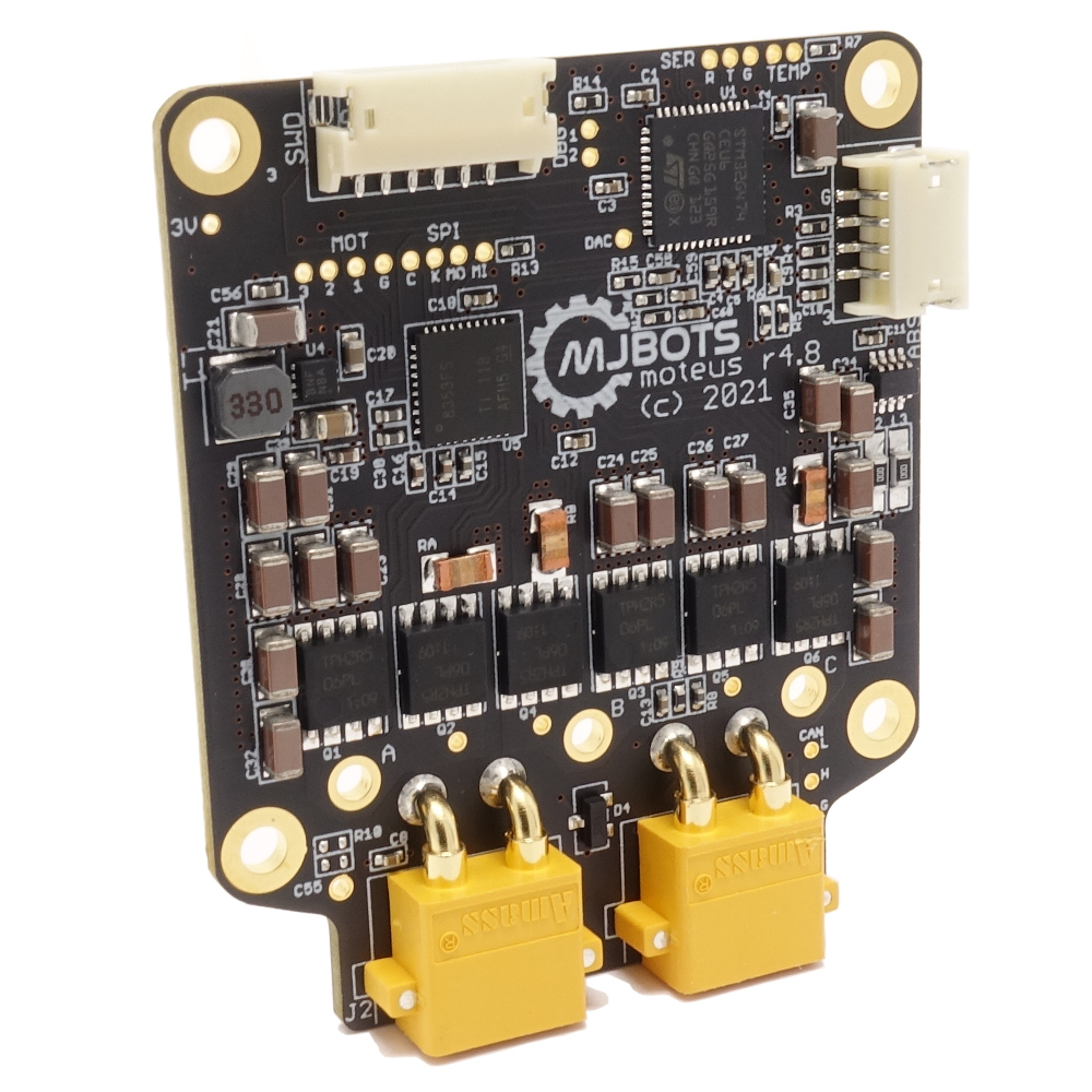
I’m excited to announce the release of moteus r4.8!

Due to the ongoing semiconductor apocalypse, this minor release uses some alternate components which were easier to source. It remains compatible with the r4.5 and r4.3 both electrically, mechanically, and with firmware.

For now, the biggest win is that the board and the devkit are actually in stock!

A secondary win is that external primary encoders are now supported, via an unpopulated connector pad on the backside of the board. I’ll write up more about that in a later post.

Spurious writes to address 0x00000000 on an STM32

What happens if you accidentally write to address 0x00000000 on an STM32 microcontroller? Answer: usually almost nothing, because most linker scripts by default map a bank of flash there, and you can’t write to flash normally. The flash controller does notice and sets an error flag, but most applications aren’t exactly checking the flash peripheral’s error flags on a regular basis.

However, if you use the HAL to try and perform a flash operation, it doesn’t bother checking the error flags *before* trying to perform an operation. It just tries, and reports any errors it observes at the end. So, if you have an application that occasionally makes a spurious write to the zero address, and also performs flash operations, it will manifest as spurious failures of the flash operations.

CAN prefixes for moteus

The moteus controller, communicates exclusively over CAN-FD for command, telemetry, and diagnostics. It will accept either standard or extended frames, and until now, the ID format in terms of bits looked like the following:

33333222222221111111100000000
43210765432107654321076543210
XXXXXXXXXXXXXQSSSSSSSDDDDDDDD

Where:

  • X: Don’t care
  • Q: 1 for query, 0 for no query
  • S: source ID
  • D: destination ID

If the lower 8 bits matched the configured ID, all the X bits would be completely ignored and moteus would accept the CAN message as if it were destined for itself. This may not be super desirable, as it consumes nearly all of the available CAN-FD addressing space.

FAB16 Festival Videos

I and the quad A1 had a great time at the FAB16 festival in Somerville this past weekend. The robot got to do a lot of running around, it and I got to meet a lot of new people, and two bands showed up!

Here’s a video of the quad A1 and Spot hanging out trying tricks:

And here’s another one of a “dance off” (kinda) with the School of Honk band. Note that although both robots collapsed at the end of this video, the quad A1 got back up and kept dancing. (Spot wasn’t broken, they just didn’t want to right it when close-ish to people). Thanks to Kathleen and Josh from BD for inviting me into their area and for being such good sports!

Working on a new leg for the quad A1 - Part 1

I’m going to try something new for this effort, and instead of making a bunch of blog posts culminating in a video, I’m going to make a bunch of intermediate progress videos. They may, but may not, culminate in an overview blog post. Here’s the first!

Gear testing fixtures

The qdd100 servo uses a planetary geartrain as the transmission reducer. This consists of an outer ring gear, an inner sun gear connected to the rotor as the input, and 3 planets connected to the output. The tolerances of these gears directly impacts the performance of the servo, namely the backlash and noise.

To date, I’ve been hand-binning these and testing each servo for noise at the end of production. To make that process a bit more deterministic, and with less fallout, I’ve built up a series of manual and semi-automated gear metrology fixtures to measure various properties of the gears.

Pocket NC power limit

I’ve been doing some machining on the Pocket NC lately to prototype some “design for manfacturing” improvements. Some time ago Q at Pocket NC posted that early versions of the v2-50 had a spindle power limit that they later decided wasn’t necessary. My v2-50 was pre-ordered at the launch, so had said limit. There was a procedure for removing it in later versions, which just required removing a single SMT resistor.