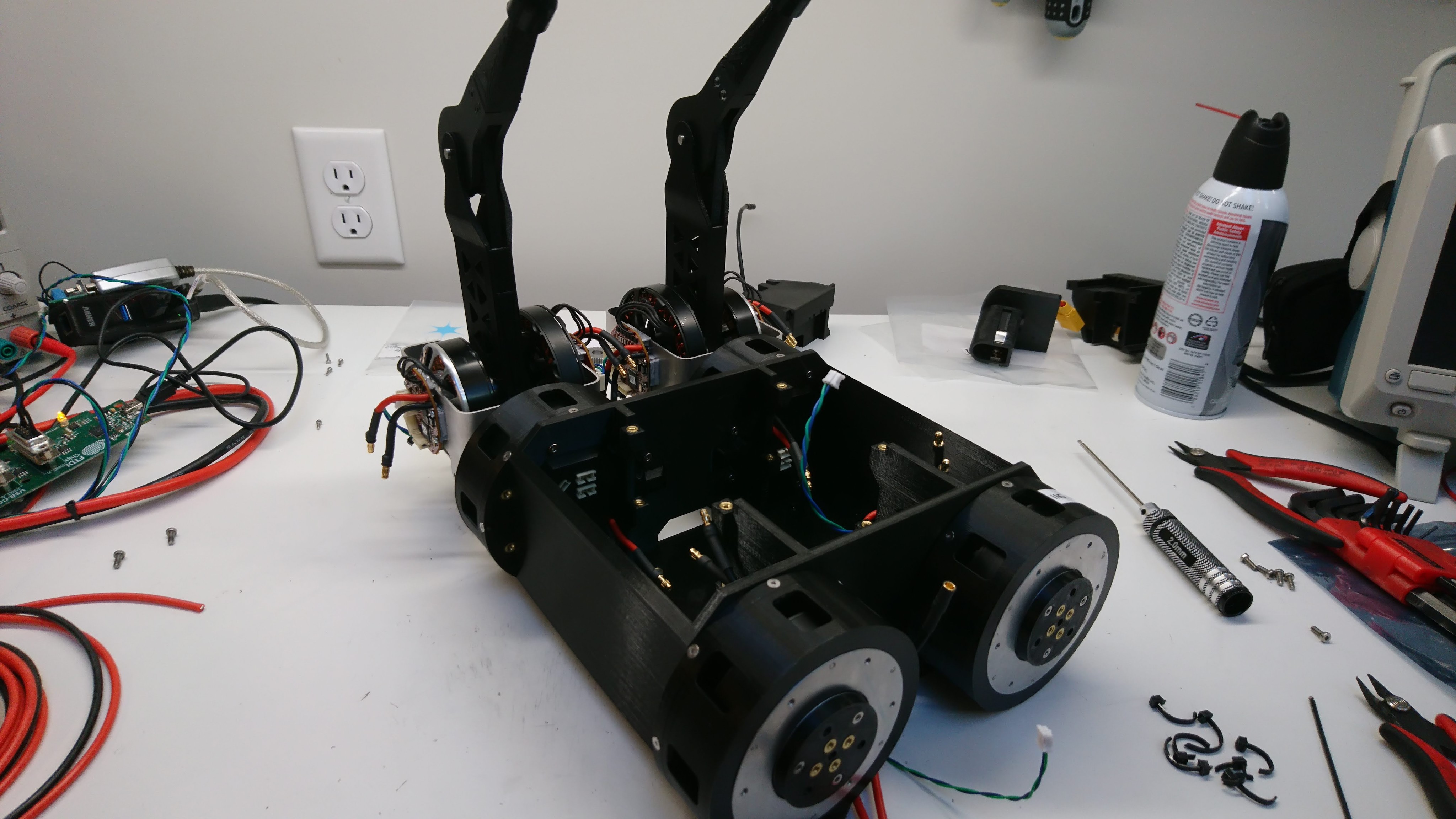
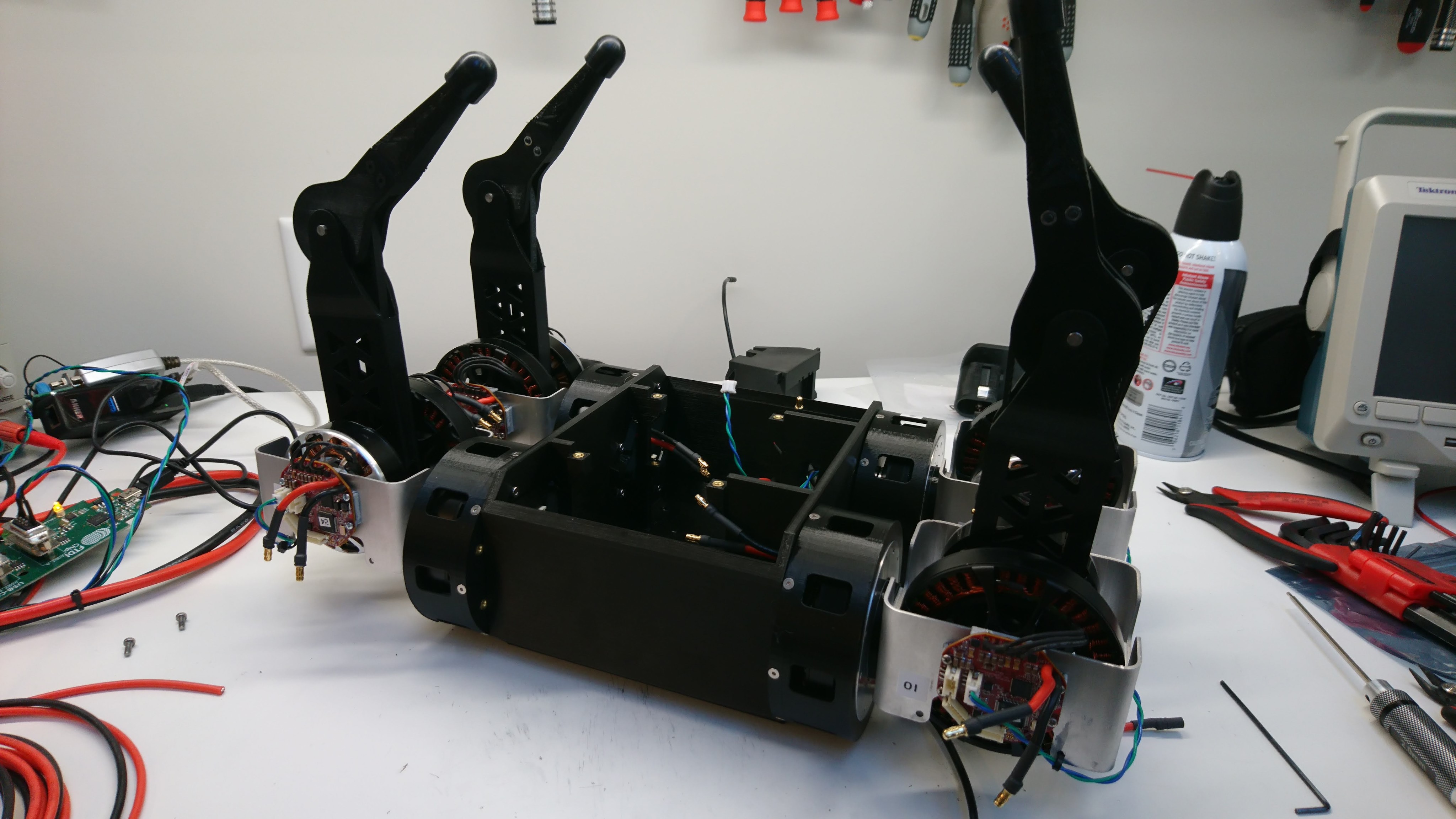
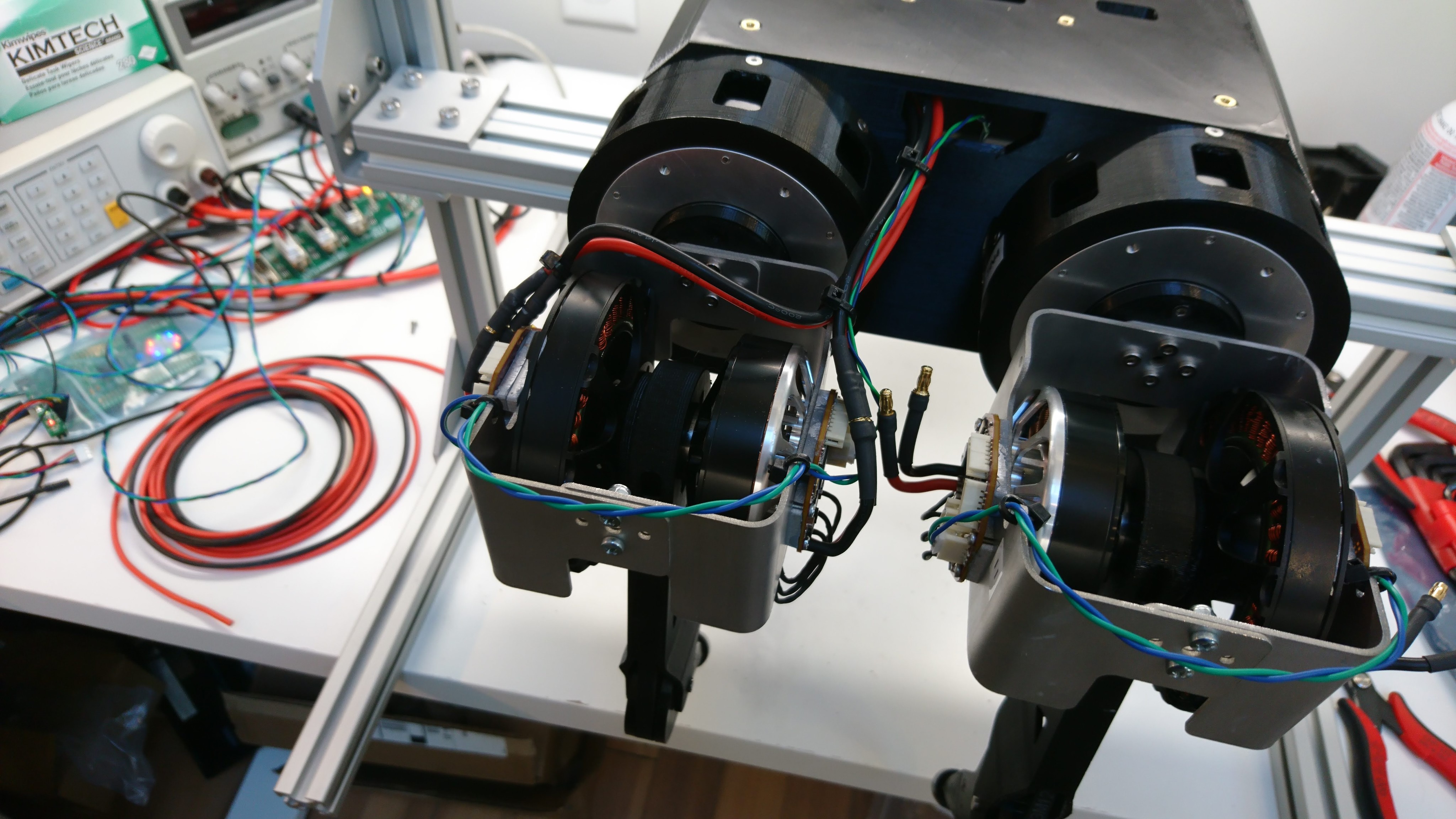
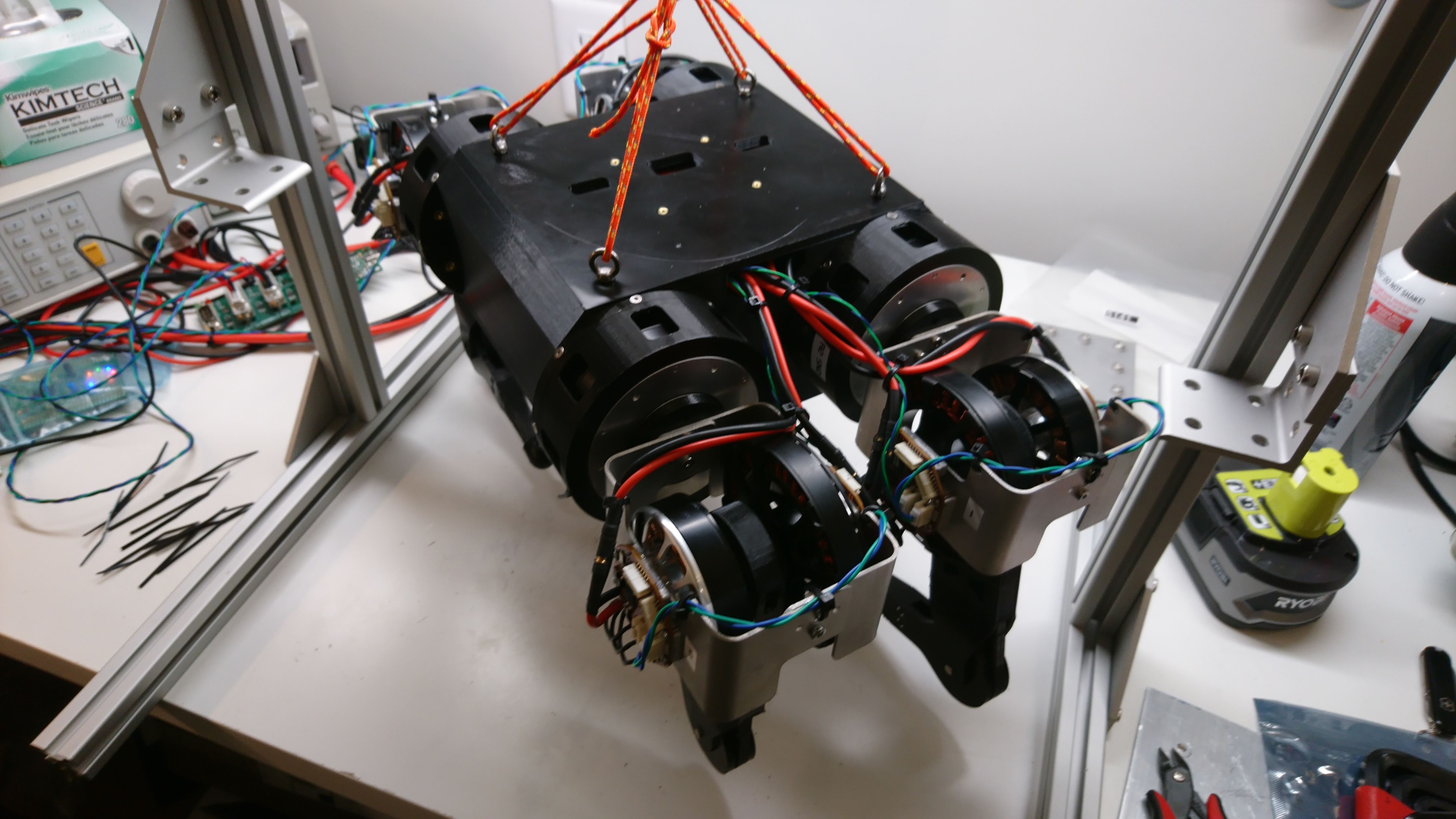
Working around motor shroud failures
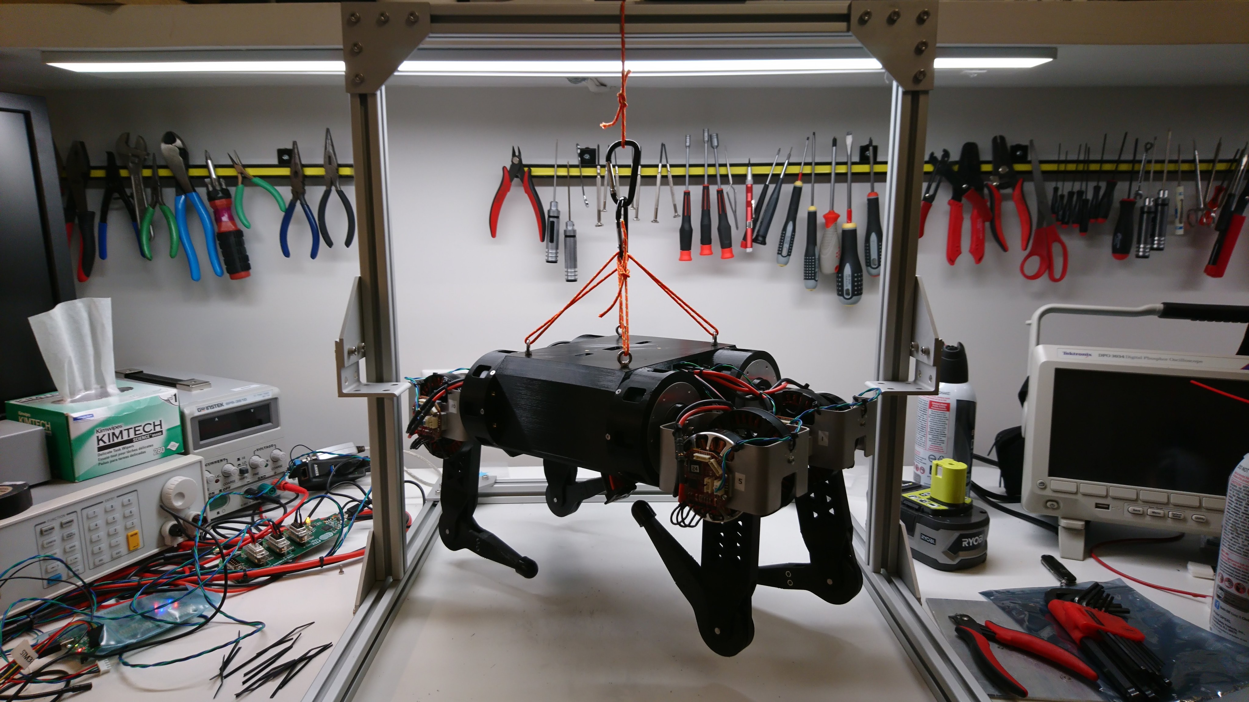
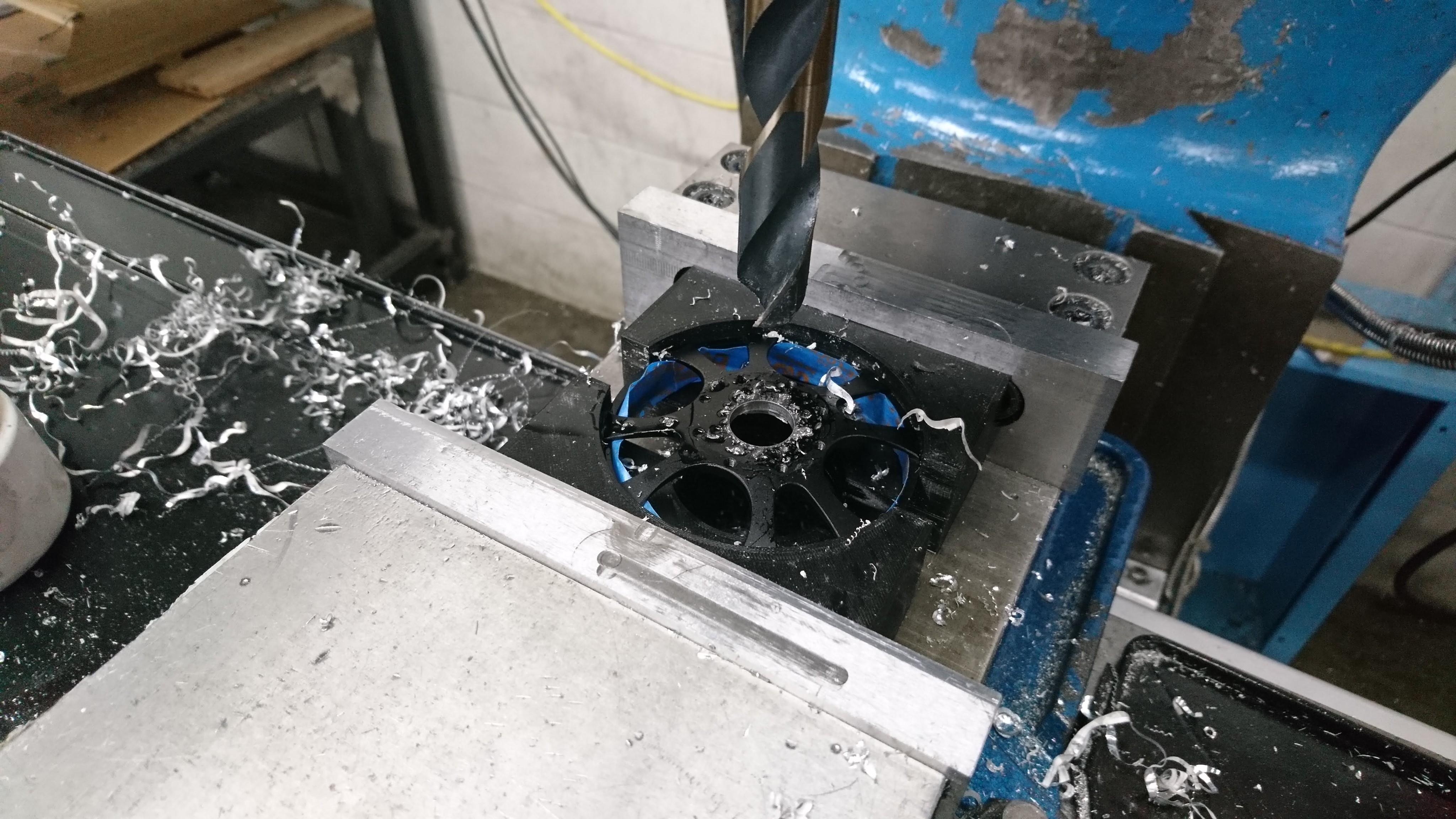
As seen at Mech Warfare 2019, the existing gearbox motor shroud isn’t really up to the task of supporting the weight of a 20lb robot. While I work on a more comprehensive redesign, I’ve got a short term fix in the form of another 3D print. This is just a simple reinforcing ring, printed at 3mm thick, with the layer lines oriented so that layer separation will not be the primary failure mode. It is attached to the outer housing via a thin layer of epoxy.