More stable acceleration limiting
Back in 2022 moteus added support for acceleration limited trajectories. This was a highly requested feature and has been used for all sorts of applications since. However when working on the recent trajectory optimization effort it became obvious that there were still some lingering stability issues on two fronts. First, when decelerating, there would occasionally be single control cycles where an acceleration was instead commanded. Second, termination at the end of a move would often involve small amounts of overshoot or oscillation. You can see both in one of the plots from that post here:
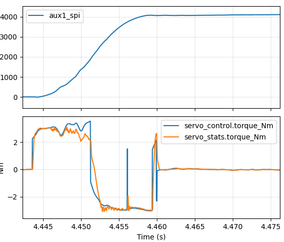
Acceleration instability
I’ve known about this for several years now, and occasionally have spent a few minutes trying to think of alternate formulations that would be more stable. With my recent attempts to use Claude Code, I thought maybe it could help here too since at least this part of the firmware is entirely tested by host side unit tests? Well, the answer was I suppose it did help, but not exactly in the way I originally intended. Read on for more details, or upgrade to moteus firmware 2026-01-21 if you just want the fixes.