Engraving on curved surfaces with the Pocket NC v2-50
I made up a YouTube video showing the techniques I used when manufacturing the beta edition of the qdd100 servos TODO link. Check it out:
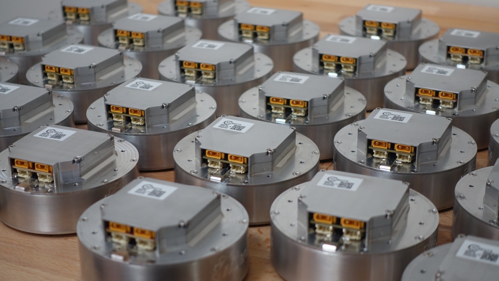
I’ve had the qdd100 beta kits available for some time up at mjbots.com, I’m excited to announce that I’ve completed a production run of the beta qdd100’s and they are now available standalone as well.
I look forward to seeing what everyone creates!

In parts 1, 2, and 3 I covered some motivation for the updated mjlib diagnostics system and the serialization of individual structures. In this post, I’ll cover how those structures are written into a file from an embedded system like a robot and how diagnostic tools can access them efficiently.
The top level goals are:
The detailed design of the log format is documented at README.md, here I will give a brief summary.
In the previous issue in this series, I described the schema and data elements of the mjlib serialization format. Here, I’ll describe the API used to convert between C++ structures and the corresponding schema and data serializations.
First, I’ll start by saying this API is far from perfect. It hits a certain tradeoff in the design space that may not be appropriate for every system. I have developed and used similar APIs professionally both at Jaybridge and TRI, so it has seen use in millions of lines of code, but not billions by any stretch. It is also mostly orthogonal to the rest of the design, and alternate serialization APIs could be built while still maintaining the performance and schema evolution properties described in parts 1 and 2. Now with that out of the way, the library API:
As discussed previously, I recently significantly revised the serialization format used by the mjbots quad A1 based on experience in previous professional domains, and from studying newer external projects like Apache AVRO. Here I’ll describe the design of the serialized representation, which is more completely defined at: mjlib/telemetry/README.md
As a brief refresher, this serialization format is intended to be used primarily to record telemetry from embedded systems, where that telemetry data may be persisted on disk for a long time. Secondarily, it can be used to inspect the results of a live system. The primitive it operates on is a “record”, which is logically a structure of elements which is emitted at some intervals over time. For any given record, it logically breaks it up into a “schema” and a “data” portion. The schema describes what types of elements are present in the structure, their names and relationships. The “data” portion contains the minimum amount of information necessary to communicate one instance of the structure, assuming that the receiver already has a copy of the schema.
Now that I have the qdd100 servo in beta phase, the IMU working at full rate, and the quad A1 is moving around I’m getting closer to actually working to improve the gaits that the machine can execute. To date, the gaits I have used completely ignore the IMU and only use the feedback from the joints in order to maintain force in 3D. With tuning and on controlled surfaces this can work well, but if you go outside the happy regime, then it can undergo significant pitch and roll movements during the leg swing phase, which at best results in a janky walk, and at worst results in oscillation or outright instability.
I used Dear Imgui for the simple Mech Warfare control application I built earlier and was relatively impressed with the conciseness with which one could develop effective (although not necessarily the prettiest), interactive and response user interfaces in C++. For some time I had been planning on developing a new diagnostic application for the mjbots quad that would allow plotting like the original tplot.py, but would also integrate recorded video and 3D rendering and diagnostics. I had assumed I would use HTML/JS because it is the cool new thing, but I never got up the energy to make it happen, because every technical step along the way had big hurdles. I figured I would give Dear Imgui a try, but the big thing it was missing was plotting support.
It seems that I’m learning much about PCB design the very hard way. Back last year I wrote up my discovery of MLCC bias derating. Now I’ll share some of my experiences with MLCC cracking on the first production moteus controllers.
When I was first putting the production moteus controllers through their test and programming sequence, I observed a failure mode that I had yet to have observe in my career (which admittedly doesn’t include much board manufacturing). When applying voltage, I got a spark and puff of magic smoke from near one of the DC link capacitors on the left hand side. In the first batch of 40 I programmed, a full 20% failed in this way, some at 24V, and a few more at a 38V test. I initially thought the problem might have been an etching issue resulting in voltage breakdown between a via and an internal ground plane, but after examining the results under the microscope and conferring with MacroFab determined the most likely cause was cracking of the MLCCs during PCB depanelization.
The quad A1 was the first robot I built with foam cast feet. When I did the first feet, I jury rigged a fixture from some old toilet paper rolls to hold things in place while they were curing. When I went to rebuild with my most recent leg geometry, I figured it was time to get at least a little more serious. Thus, my new leg casting fixture:

When an insert is cast into place, it is set on one of the trays, the tray is inserted into a slot, and then a weight can be placed on top and constrained by the fixture.
Continuing in my series of developments with the Mech Warfare turret, I’ve now managed to replicate the primitive target tracking functionality I had in the v2 version of the turret. This works using a pretty simple principle:
This works passably, as shown in the video below: