Building the quad A1
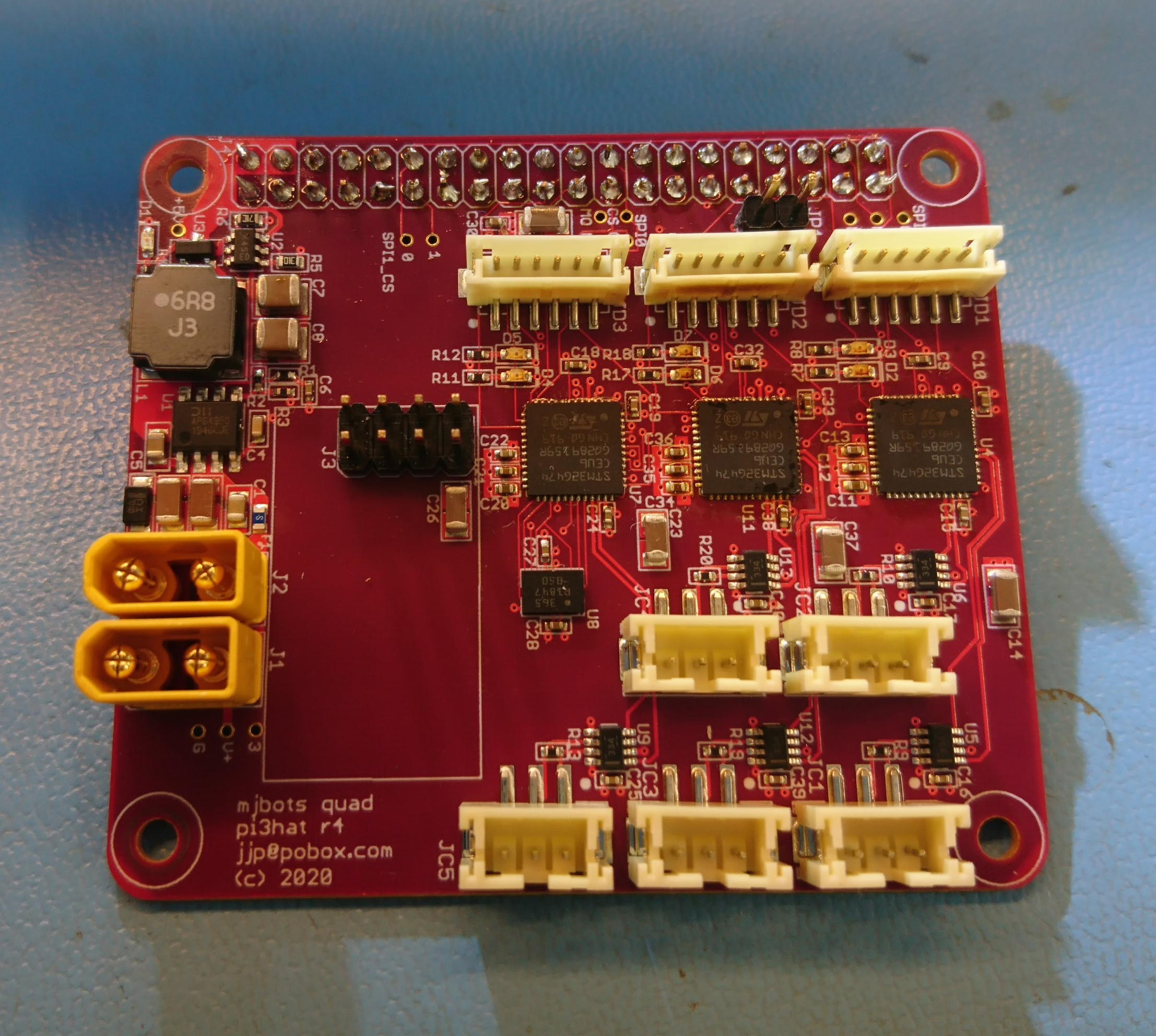
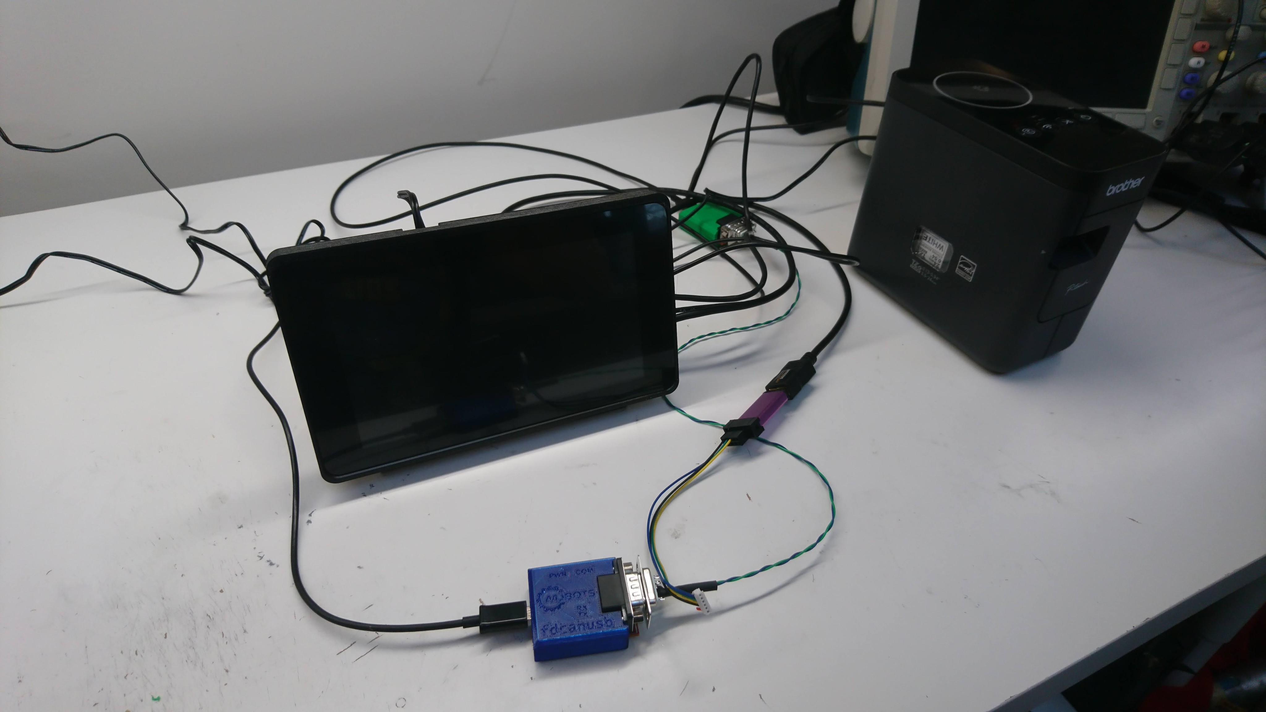
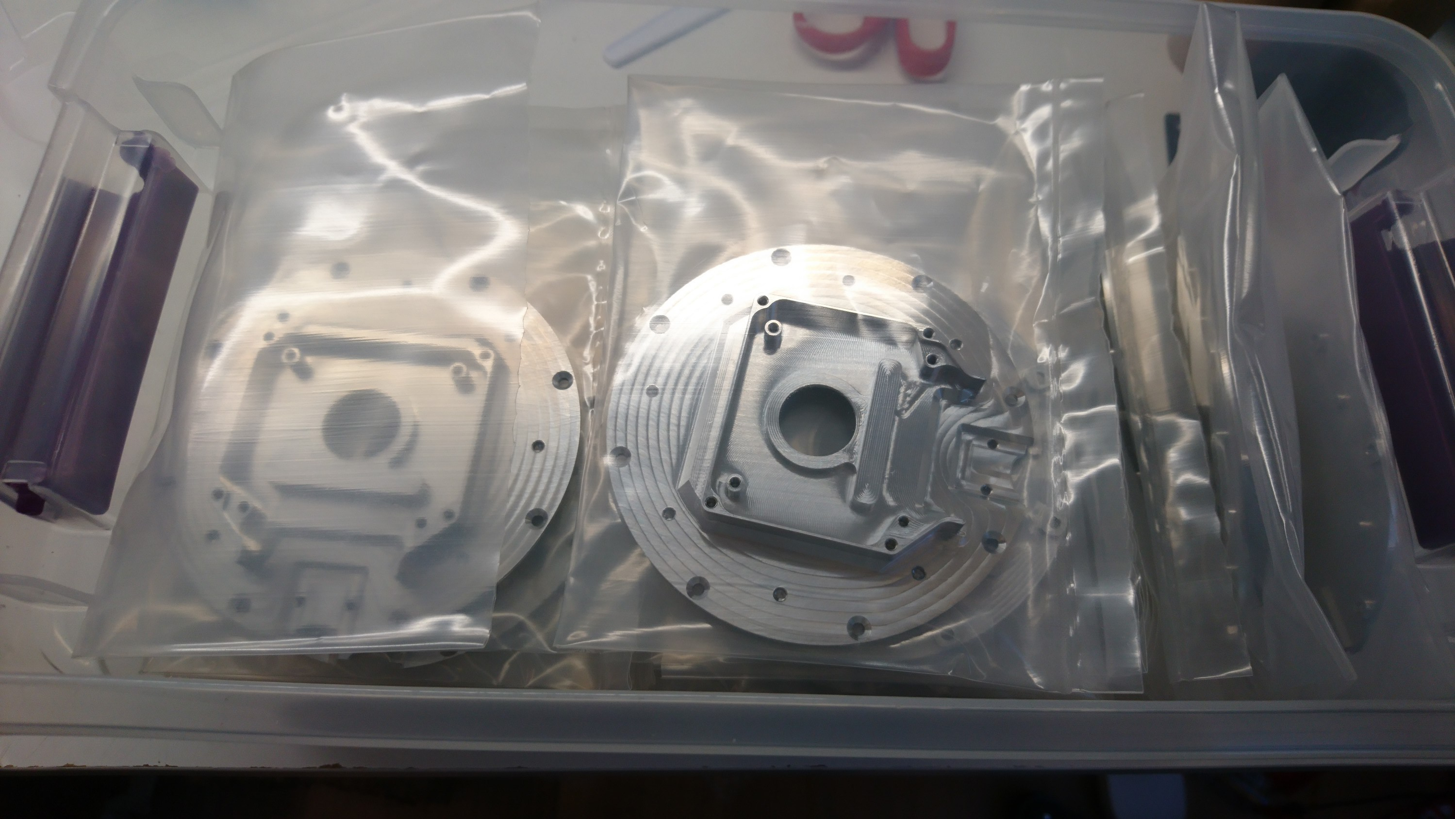
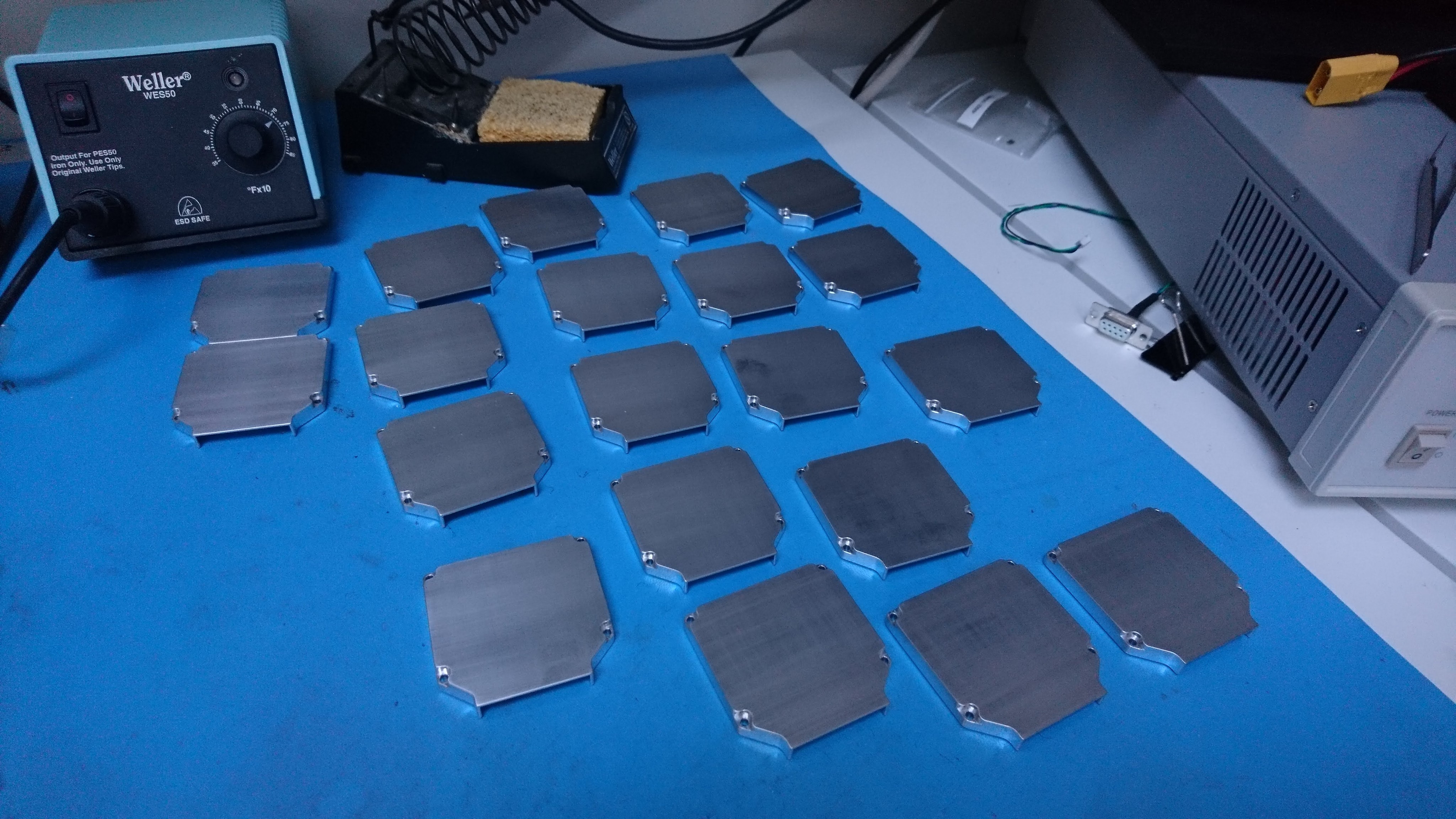
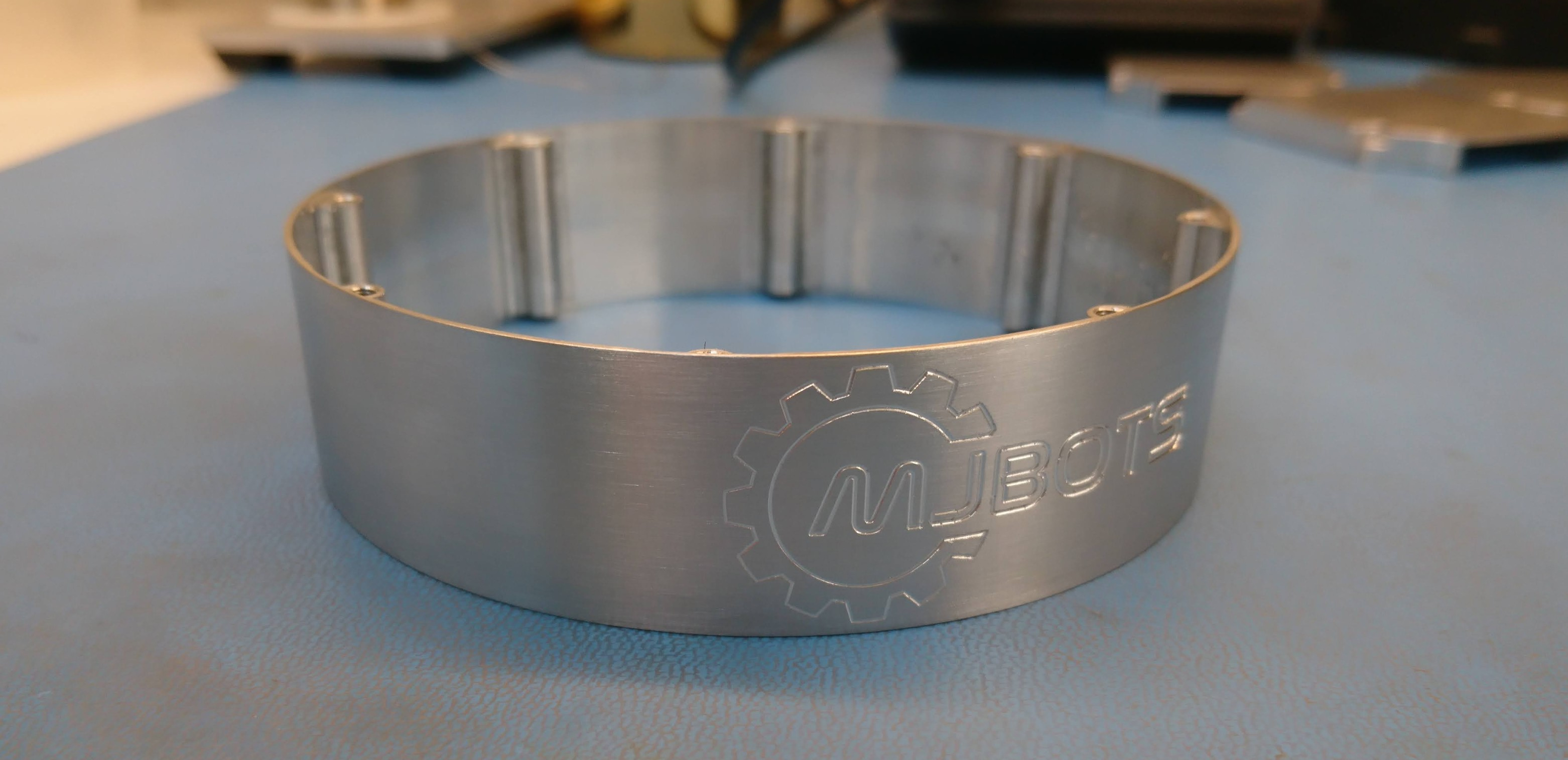
Now that I have a bunch of the mk2 servos set and ready to go, a new leg design, a new power distribution board to power them, and a raspberry pi3 hat to communicate with them, I built a new quadruped! I’m calling this the mjbots quad A1, since basically everything is upgraded.
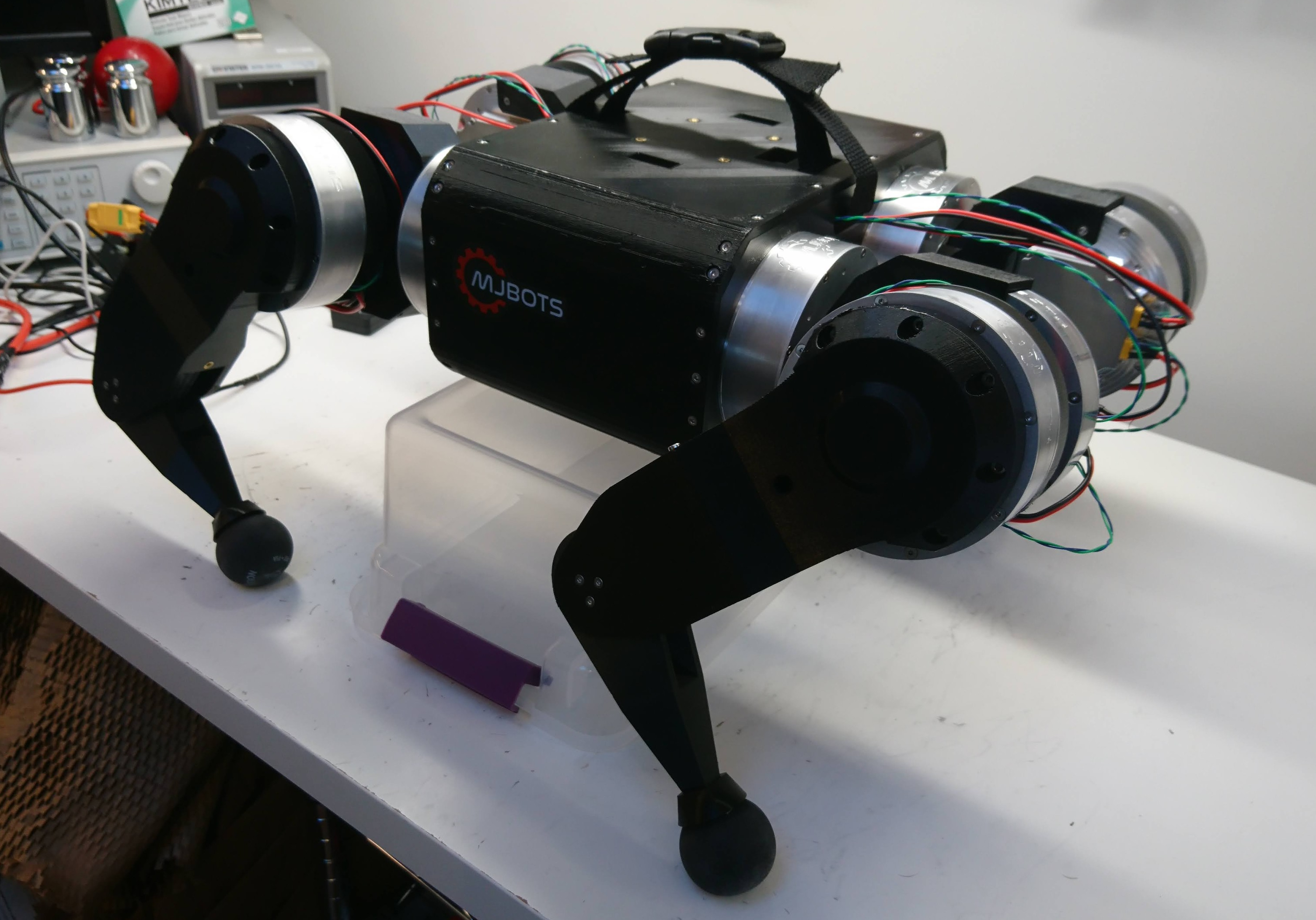
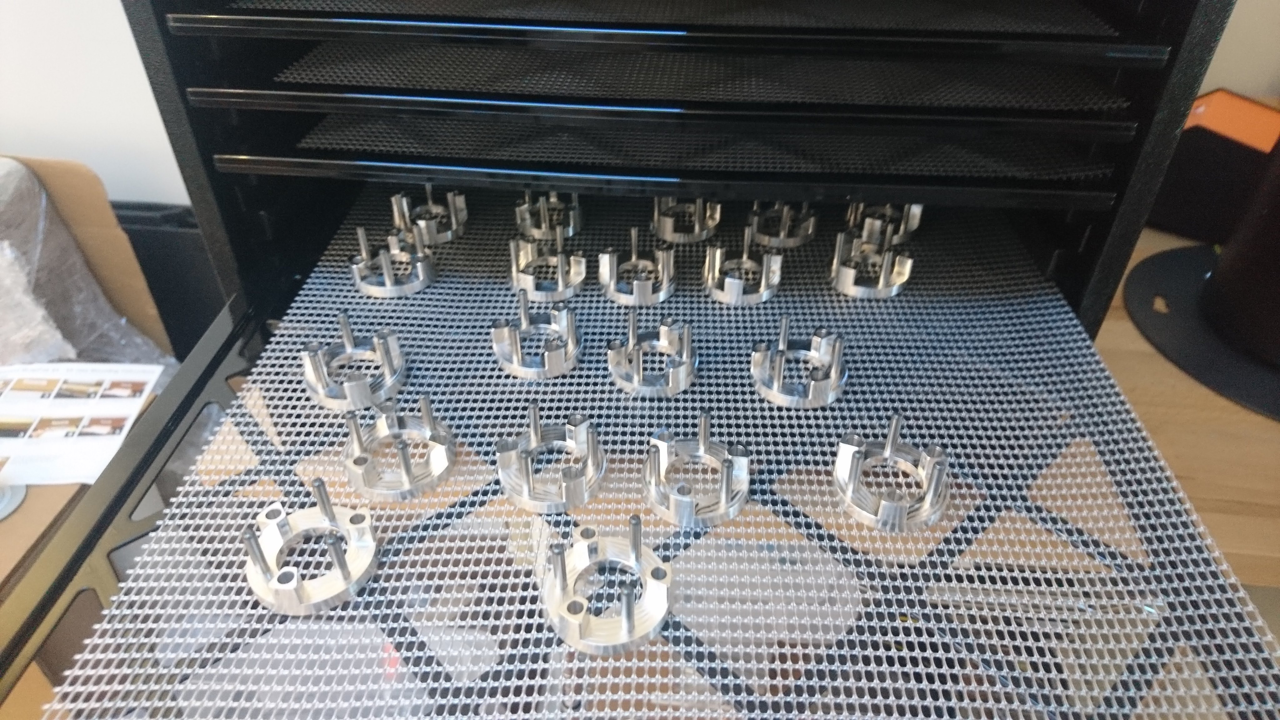
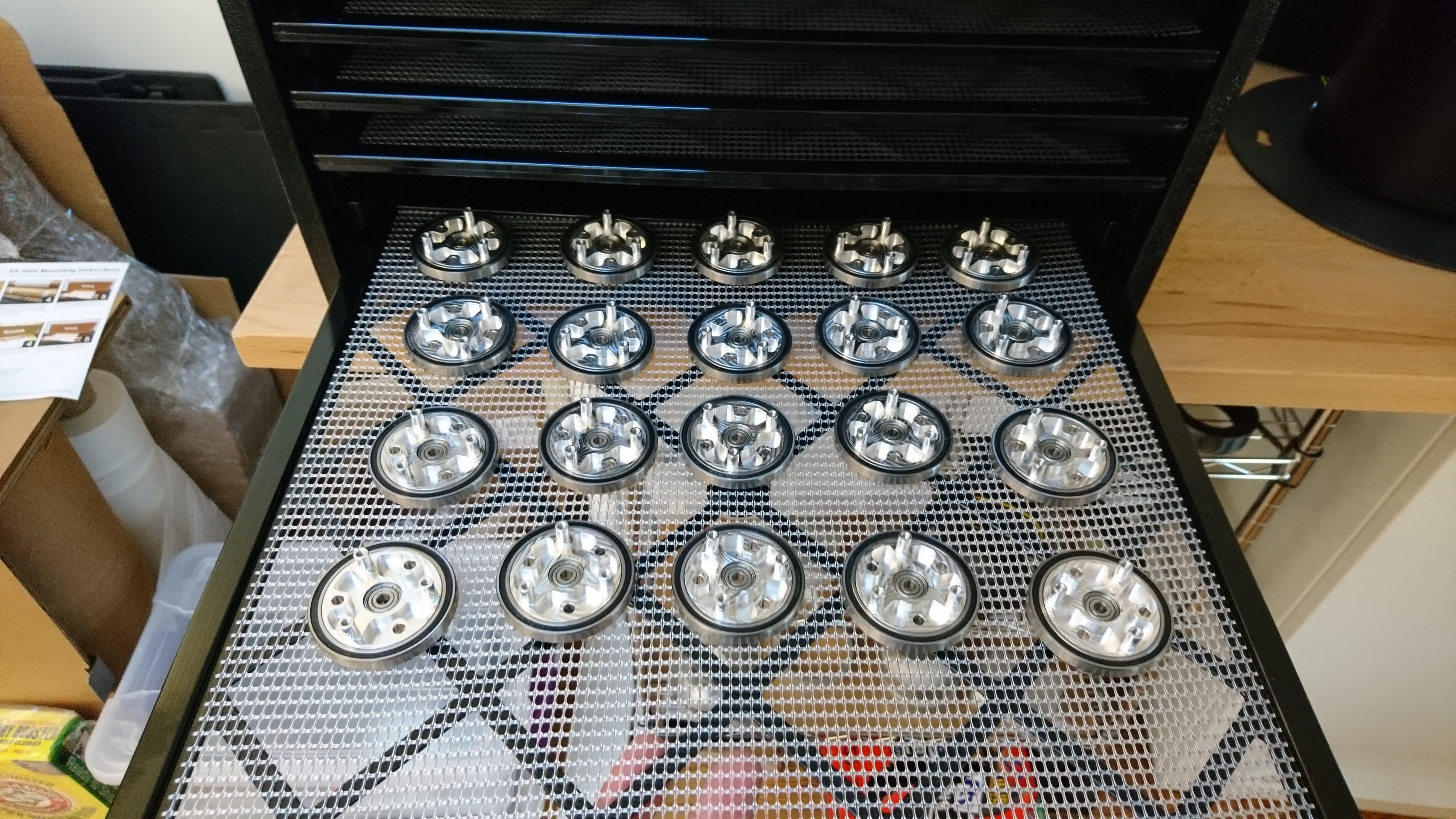
After I initially assembled the new legs onto the chassis, I realized I had the geometry slightly off and there was some interference through part of the shoulder rotation. I made up new printed parts and replaced everything in front of the camera. Thus, watch some high speed robot surgery: