All parts received!
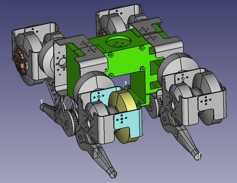
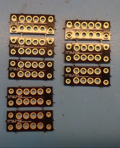
I’ve now managed to get all the custom and long lead time parts in house for the first version of a quadruped based on the new actuators I’ve been designing.
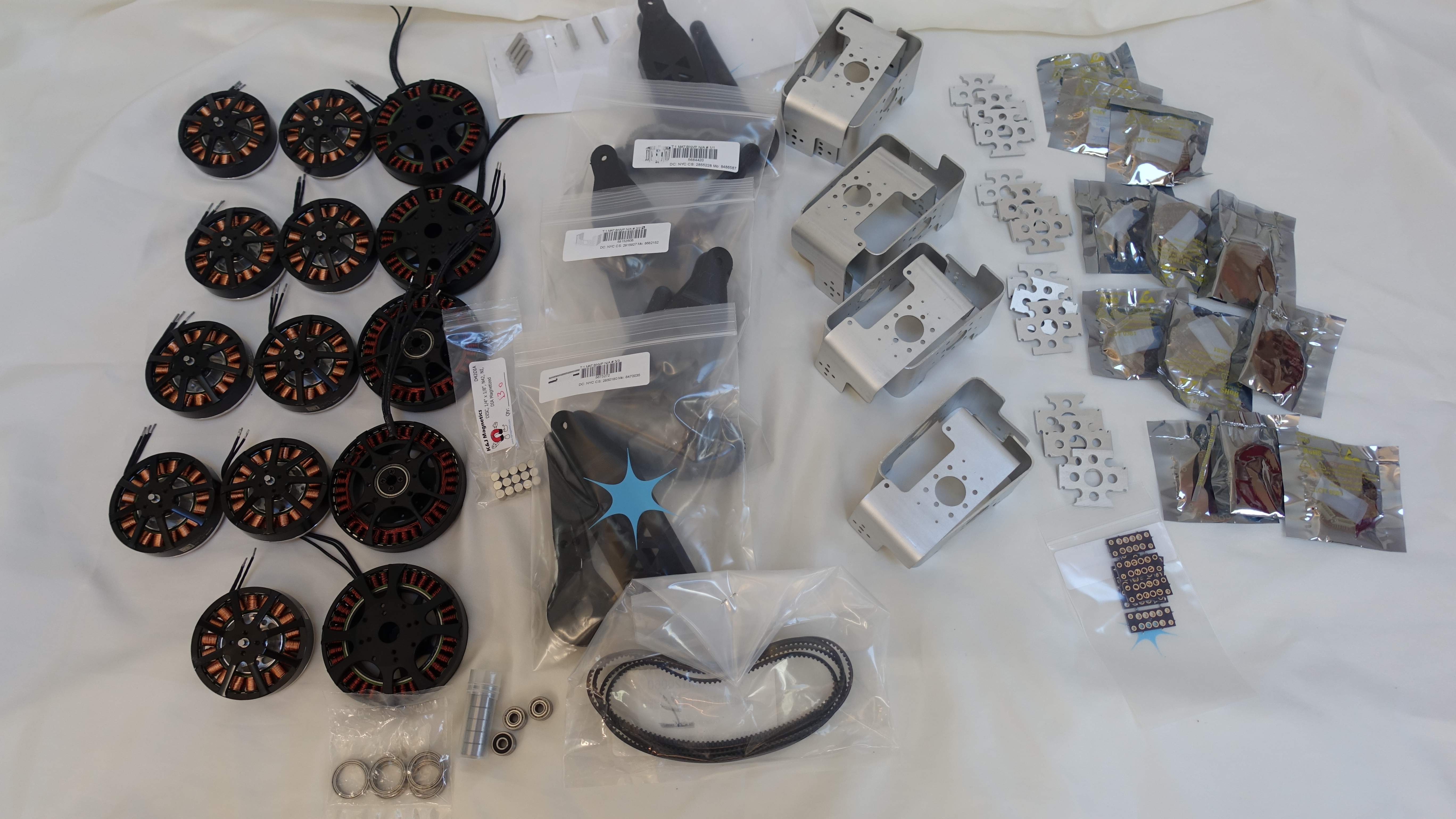
All The Parts!
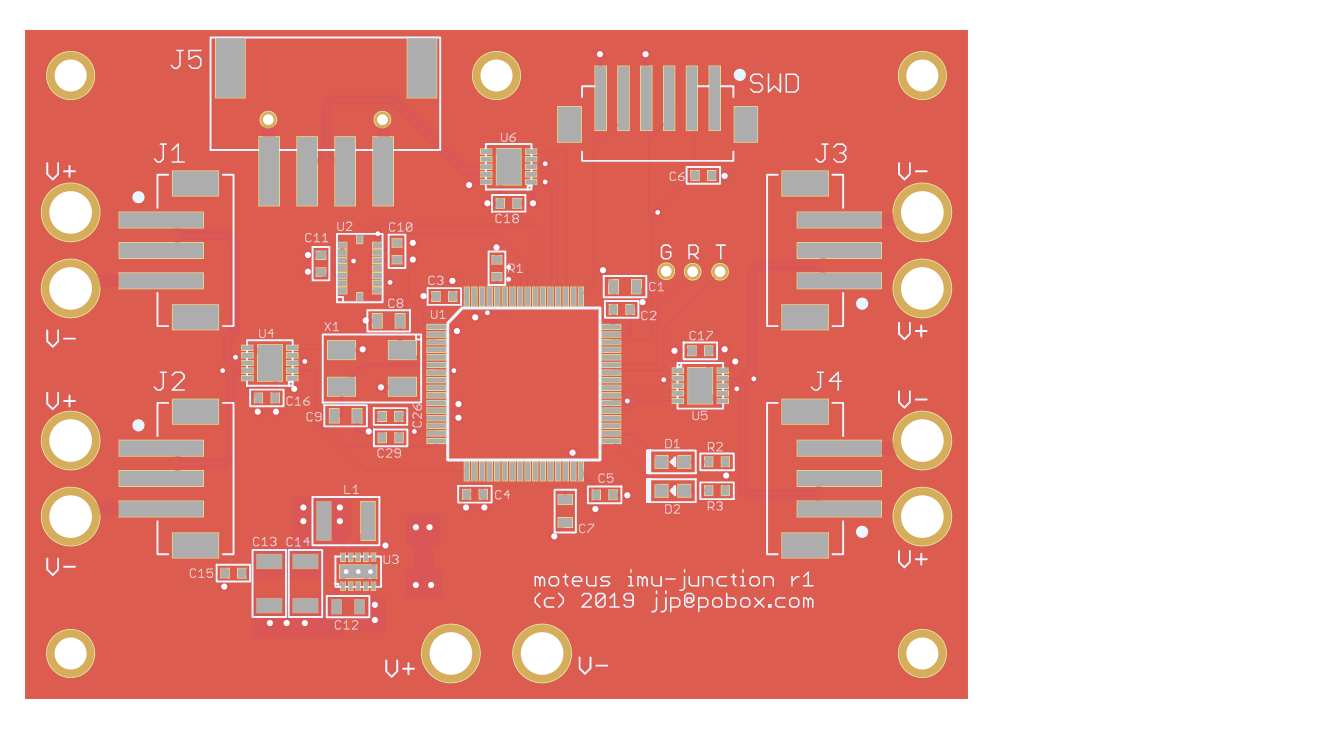
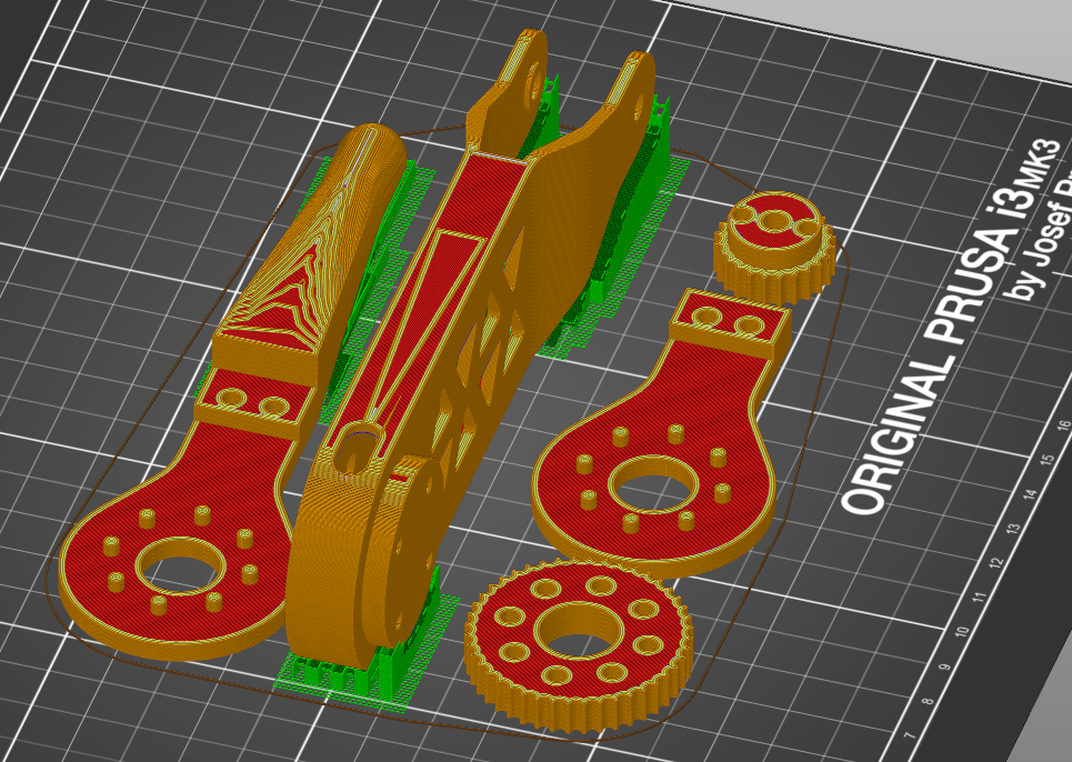
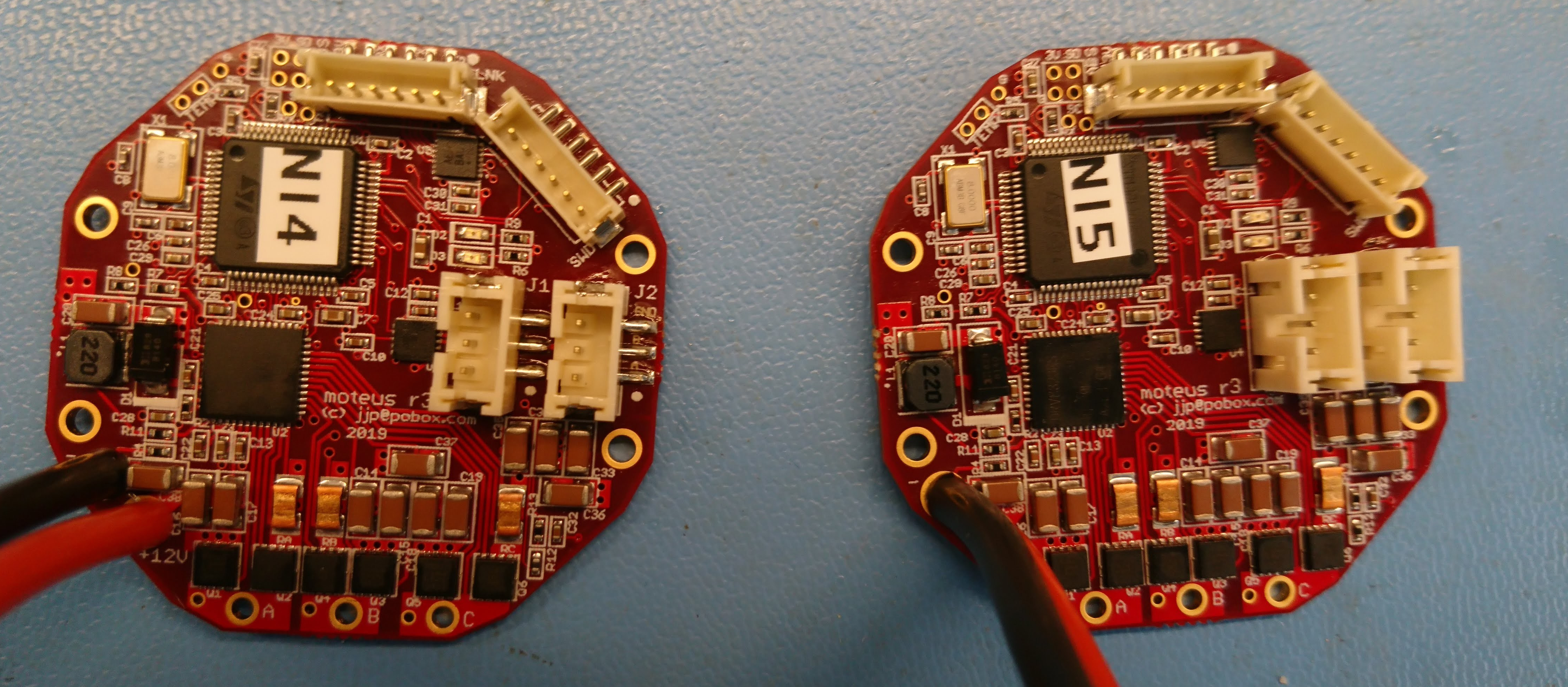
That includes all the motors, custom brackets, and at least moderately working versions of all the custom PCBs. Now I just have to get the local rework done, get the software into a semi-reasonable state, and put it all together!